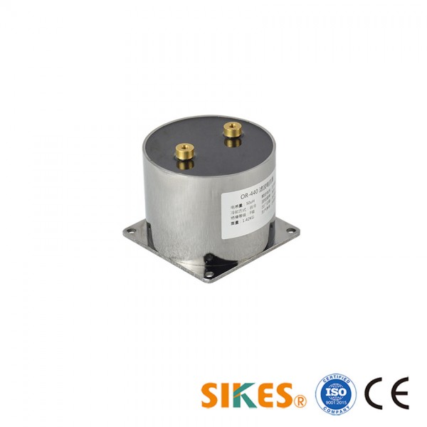
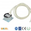
High frequency DC filterling reactors for high-speed maglev train 60A
Application principle and description
High frequency DC filterling reactors are mainly used to limit high frequency harmonics and suppress the voltage impact of the input circuit on the electromagnet. The application circuit of the reactor is shown in the following diagram. This circuit is a half-bridge chopper circuit. The reactor is connected in series with the load electromagnet. The system input voltage is DC270V~DC660V, two IGBTs are turned on or turned off at the same time. The current direction is shown as diagram when turned on. The diode will keep the current direction in reactor and electromagnet remains unchanged when turned off. However, there is a voltage surge at the moment of switching on and off, and the reactor should meet the switching frequency requirement of IGBT at least 5KHz.
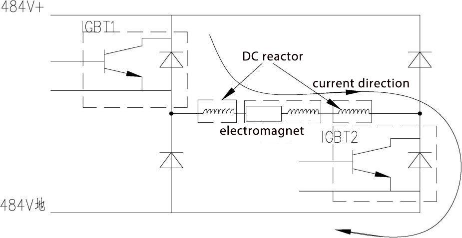
Circuit Diagram
Application:
Reactor for suspension controller of 600 km/h high-speed maglev train, installed inside the interlayer at the bottom of maglev train.
Main features
Total loss: less than 60W (150 ℃).
MTBF ≥1000000h
Service Life ≥30 years
Standard:
GB/T 191-2008
GB1094.1-1996
GB1094.3-2003
GB/T 4798.5-2007
GB/T 5465.2-2008
GB7328-1987
GB/T 25120-2010
GB/T 21563-2008
DIN5510-2-2003
DIN 5510-5
EN 15085-2:2007
EN 50126-1999
TJ/CJ 254-2013
GB/T 21413.1
EN45545-2-2013
| Filter | |
| AC/DC | DC |
| Choke | |
| Nominal voltage range(V) | 660 |
| Nominal Current range(A) | 60 |
This is a Demo Shop. You can place your order, but please contact us before you pay.

